How Breadboards Work
A breadboard is the canvas to designing circuits. In a breadboard there is a red positive side and a blue negative side. After connecting this to a battery using wires, you can experiment building circuits. Connecting the battery to the bread board, power is sent through the same half side of the bread board where the battery is connected. Then, using tools such as LEDs, switches, potentiometers, and more, you can build a circuit.
Below is a video of my circuit working.
Below is a picture of the schematics for the circuit.
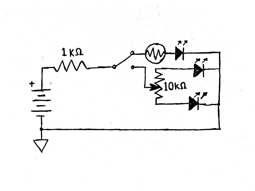
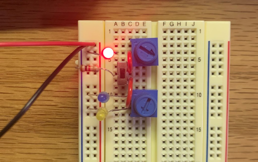
For the bonus part of the lab, I got another potentiometer and replaced it with the photo cell. I was successfully able to change the brightness of the additional LED controllable with the potentiometer along with the other two LED on the bottom. Below is a picture of the circuit.
Multimeters
The main purpose of a multimeter is to measure voltage, current, and resistance. Multimeters can come in handy while working with circuits when there is something wrong with the circuit and you want to check if there is power running through certain parts of the circuit. By doing this, it is easier to find the problem and fix it without going through a bigger failure with the circuit.
Analog Circuit Troubleshooting Notes
Building this circuit, I had a couple errors before making my final circuit. The first mistake I made with my circuit was while I was connecting my photo cell to the switch, I connected the photo cell to the middle hole instead of the top hole. This ended up making the top LED connected to the photo cell to be always on. I quickly saw my mistake with the connection and fixed it to make it work. The second problem I had to think about before building my circuit was how to use only one resistor for the circuit. After reviewing the circuits I built in class, I was able to place the resistor directly in the beginning course of the circuit and find it work.
Final Project
Ryan Mahany- This project looked interesting to me because of the tremolo effect that he made was changed based on the volume of the input signal. Also, the using a guitar on this effect really made it appealing. Looking at the schematics, there are many parts that I don’t understand yet, but looking at the descriptions for each parts I was able to understand how they each worked in the circuit.
David Kim – For his final project, David built a synthesizer with arcade buttons. This project, visually, was very appealing. It was also interesting to me that there were so many things that he could change with the sound on the circuit himself. He was able to change the pitch, vibrato, and a tremolo. Nonetheless, his schematics for the circuit is very complicated with multiple series of resistors.
Cameron Koo – Cameron built a filter that can cut certain frequencies. Using sliders instead of knobs to make it easier to use made the project look more simple. It was interesting to see the way he divided his circuit into five sections and describe each part. Also, the audio demo of this circuit was very fun to listen to.
